3-State Alarm System
This project implements a residential security control system based on a synchronous hardware architecture. The core of the design is a finite state machine that manages three operation modes: Disarmed, Armed, and Active Alarm.
Source Code:
https://github.com/SimonAulet/portfolio/tree/main/FPGA/Alarm
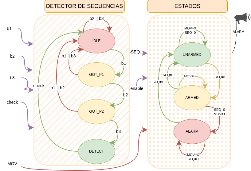
System architecture: signal flow between sequence detection and state control.
Control Logic and Operation
The user interface consists of three combination buttons (b1, b2, b3) and a validation command (check). The system evaluates the entered sequence only when validation is pressed, enabling robust control logic: if the user attempts to validate an incorrect sequence while the system is armed, the transition is immediate to the Alarm state. Similarly, the alert state triggers upon motion sensor activation (MOV).
Synchronization Strategy
To ensure operational stability within the FPGA and avoid creating multiple clock domains, a synchronous enable strategy was chosen. Instead of dividing the main clock line—with its corresponding timing issues—the freq_divider module was implemented.
This component generates single-cycle pulses ("ticks") that enable processes at lower frequencies (such as 1 kHz and 1 Hz), keeping the entire design perfectly synchronized to the 100 MHz master clock. Additionally, the module is fully parameterizable, allowing adjustment of division scales to accelerate times during simulation stages or define final values for synthesis.
Expand code: Tick Generator (freq_divider.v)
always @(posedge clk_in)
                  // Pulse generator at 1kHz and 1 Hz

                  module freq_divider #(
                    parameter mf_divider = 100_000,
                    parameter lf_divider = 1_000)
                  (
                  input  wire clk_in,
                  output reg  tick_mf,
                  output reg  tick_lf
                  );

                  reg [18:0] mf_counter;
                  reg [8:0] lf_counter;

                  initial
                  begin
                    tick_mf    = 0;
                    tick_lf    = 0;
                    mf_counter = 0;
                    lf_counter = 0;
                  end
                  // Counter advancing
                  always @(posedge clk_in)
                  begin
                    if (mf_counter == mf_divider - 1) //mf counter. division is for switching posedge and negedge
                    begin
                      mf_counter    <= 0;
                      if(lf_counter == lf_divider - 1) //lf counter
                        lf_counter  <= 0;
                      else
                        lf_counter <= lf_counter + 1;
                    end else begin
                      mf_counter   <= mf_counter + 1;
                    end
                  end

                  // Freq divider lf
                  always @(posedge clk_in)
                  begin
                    if((lf_counter == 0) && (mf_counter==0))
                      tick_lf <= 1'b1;
                    else
                      tick_lf <= 1'b0;
                  end
                  // Freq divider mf
                  always@(posedge clk_in)
                  begin
                    if(mf_counter == 0)
                      tick_mf <= 1'b1;
                    else
                      tick_mf <= 1'b0;
                  end
                  endmodule
                end
Resource Optimization
Input signal conditioning directly benefits from the previous synchronization strategy. The anti_bounce module uses 1 kHz ticks as a temporal reference to filter mechanical noise from buttons. This design decision allows significant reduction in register usage: the 20 ms stability window is managed with a compact 6-bit counter, avoiding the need for 21-bit counters that would be required if operating directly on the 100 MHz base frequency.
Verification
System reliability was ensured through an incremental validation methodology. Modules were subjected to dedicated testbenches to verify correct operation before final integration into the top-level entity.
Light Sequencer (Moore Machine)
This design implements a light effect sequencer controlled by a single button. The architecture is strictly based on the Moore Machine model, where outputs depend exclusively on the current state and not on direct inputs.
Source Code:
https://github.com/SimonAulet/portfolio/tree/main/FPGA/Sequencer
Decoupled Architecture
To maximize modularity, the system was divided into two independent functional blocks operating under the same clock domain (100 MHz), synchronized through enable signals (ticks) inherited from the previous design:
- State Control (
state_change.v): Manages button reading, debouncing (usingtick_mf), and state transitions. - Output Decoding (
led_change.v): Interprets the current state and generates corresponding visual patterns.
Transition and Output Logic
The system cycles through 4 operational states with each validated button press. The output logic leverages the low-frequency signal (
This separation allows altering light patterns (e.g., changing frequency or bit pattern) by modifying only the output module, without risk of altering the flow control logic. |
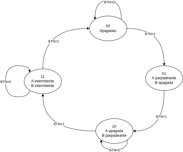
Sequencer state diagram (Moore) |
Expand code: Output Logic (led_change.v)
module led_change(
                  input  wire[1:0] state,
                  input  wire      clk,
                  input  wire      tick_lf,
                  output reg       led_a,
                  output reg       led_b
                );

                initial
                begin
                  led_a = 1'b0;
                  led_b = 1'b0;
                end

                always@(posedge clk)
                  case(state)
                  2'b00:
                  begin
                    led_a <= 0;
                    led_b <= 0;
                  end
                  2'b01:
                  begin
                    if(tick_lf)
                      led_a <= ~led_a;
                    else
                      led_a <= led_a;
                    led_b <= 0;
                  end
                  2'b10:
                  begin
                    led_a <= 0;
                    if(tick_lf)
                      led_b <= ~led_b;
                    else
                      led_b <= led_b;
                  end
                  2'b11:
                  begin
                    if(tick_lf)
                      led_a <= ~led_a;
                    else
                      led_a <= led_a;
                      led_b <= led_a;  //copy led_a to avoid mirror blink
                  end
                  default:
                  begin
                    led_a <= 0;
                    led_b <= 0;
                  end
                endcase
                endmodule
Verilog Fundamentals
This section explores digital hardware construction from its most elementary blocks, focusing on modularity, parameterization, and state machines.
Source Code:
https://github.com/SimonAulet/portfolio/tree/main/FPGA/Verilog
Hierarchical Design: Full Adder (Ex. 10 and 11)This module illustrates the "bottom-up" design methodology. Instead of describing the full adder logic at once, it was built by encapsulating lower-level components:
This structure allows easy scaling to a 4-bit Adder (Ripple Carry) by reusing the validated module, fundamental basis for the ALU. |
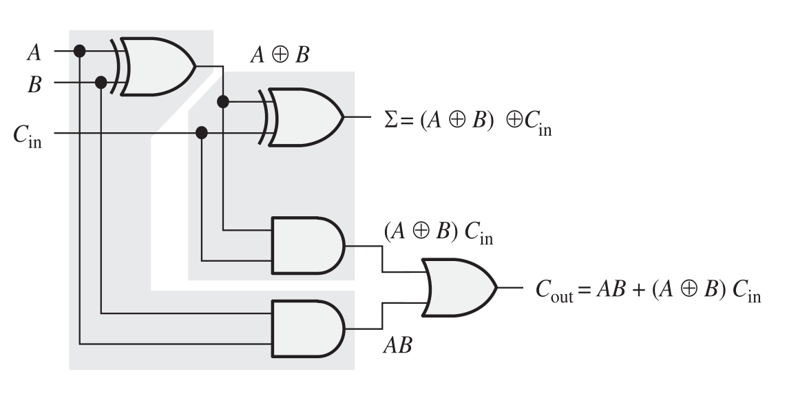
Architecture with 2 Half-Adders 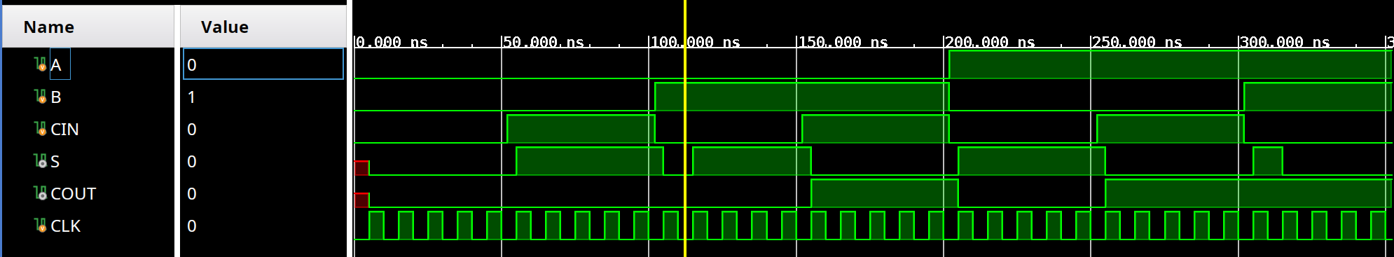
Truth table validation |
4-Bit Arithmetic Logic Unit (ALU) (Ex. 12)Integration of arithmetic and logical combinational logic in a single core. The ALU performs 4 selectable operations through a 2-bit Opcode:
Simulations validate both signed handling (decimal format) and bitwise operation (binary format). |
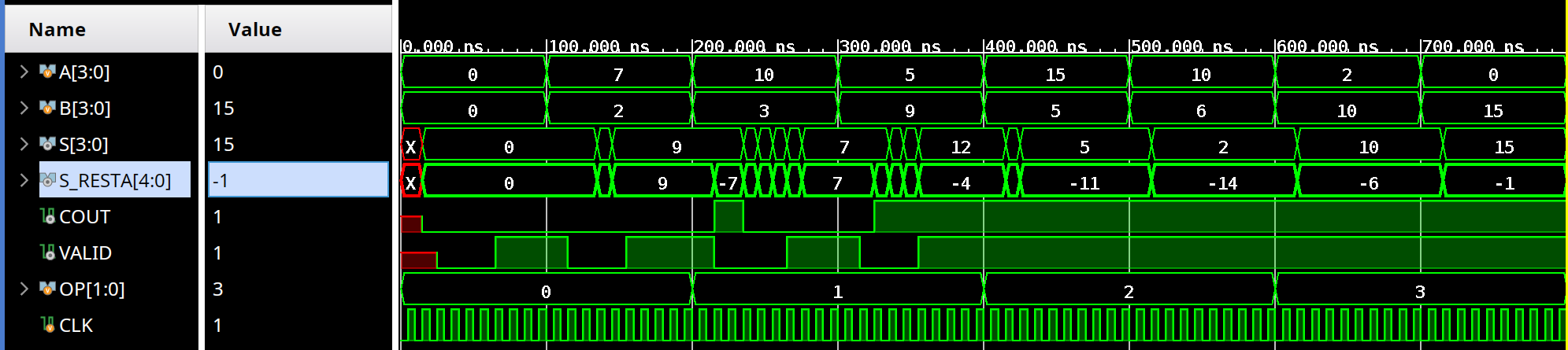
Arithmetic: Addition and Subtraction (Signed) 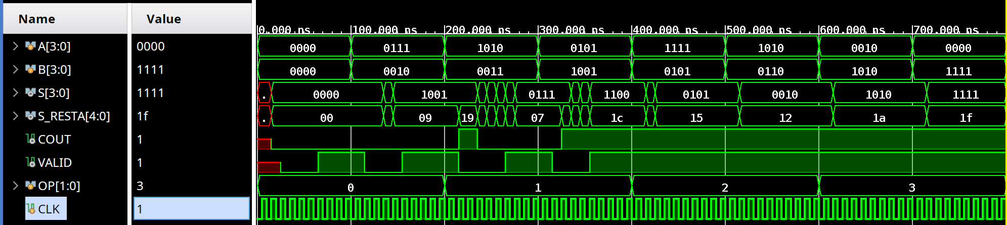
Logic: AND and OR (Bitwise) |
Parameterizable "Module-N" Counter (Ex. 18)A flexible sequential logic design that allows defining the count limit (N) dynamically through an 8-bit input. Three critical scenarios were validated:
|
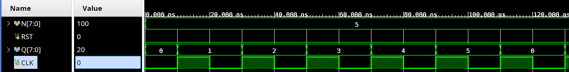
1. Count start (0 to 5) 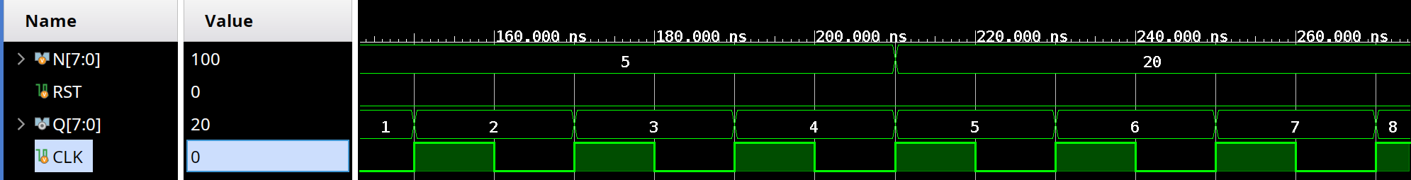
2. N change "on-the-fly" 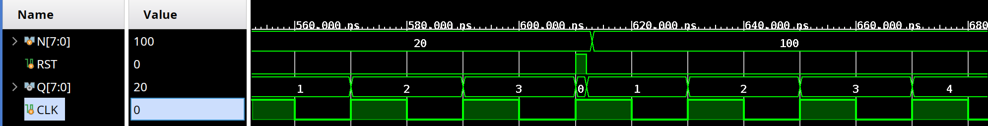
3. Asynchronous Reset |
"101" Sequence Detector (Ex. 20)Implementation of a Moore State Machine that analyzes a serial input bit by bit.
Designed to allow overlap. For example, in the sequence |
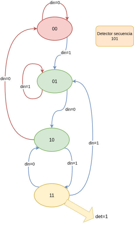
|