1. Half-Wave Dipole Antenna (λ/2) - Tuned
Configuration: Thin center-fed dipole, oriented along Z-axis. Final dimensions optimized through parameter sweep.
1.1 Parameters at 1 GHz
| Parameter | Value |
|---|---|
| Resonance frequency | 1.0 GHz |
| Minimum S11 | -28.0 dB |
| Maximum directivity | 2.12 dBi |
| Total efficiency | -0.1715 dB (∼96%) |
| Radiation efficiency | 0.001466 dB (∼99.9%) |
| Beamwidth (-3 dB) - E-plane | 78.3° |
1.2 3D Radiation Pattern and Principal Cuts
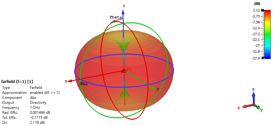
Figure 1.1 - 3D radiation pattern. Logarithmic scale visualization of directivity. Shows the characteristic toroidal ("donut") pattern, with maxima in the equatorial plane (XY) and nulls along the dipole axis (Z). This result corresponds to the tuned dipole length after a parametric sweep (parameter sweep).
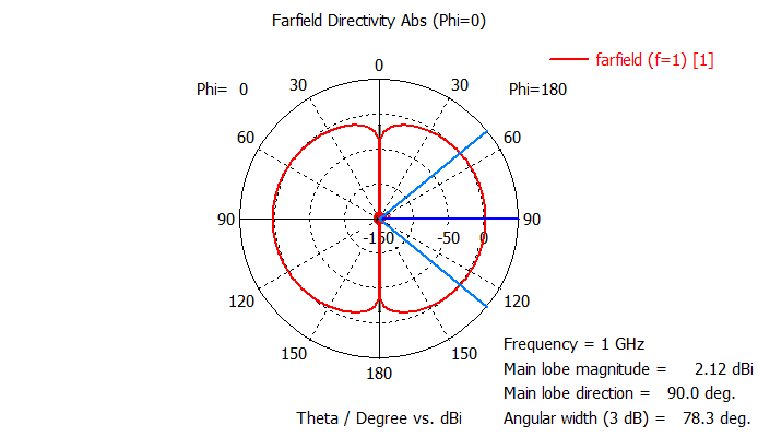
Figure 1.2 - E-plane Cut (φ=0°) |
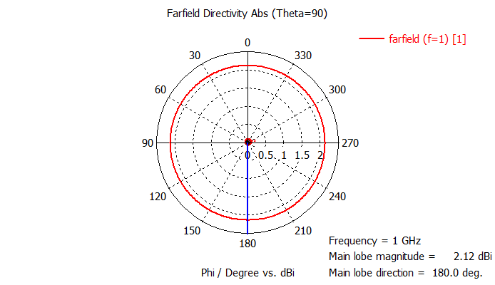
Figure 1.3 - H-plane Cut (θ=90°) |
Figure 1.2 & 1.3 - E and H-plane patterns. The cut in the E-plane (containing the dipole) shows the classic two-lobe pattern with a beamwidth of 78.3°. The cut in the H-plane (perpendicular to the dipole) validates the theoretical omnidirectionality.
1.3 Optimization and Frequency Response
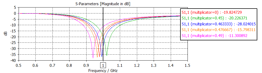
Figure 1.4 - Impedance optimization. S11 parameter curve for the optimal length factor (0.463333λ), obtained after a parametric sweep (mult. from 0.45 to 0.49λ). The minimum of -28 dB at 1 GHz confirms the precise tuning achieved and optimal impedance matching.
1.4 Design Conclusion
The dipole was systematically modeled and optimized through a parameter sweep of its length, achieving precise resonance at 1 GHz with an S11 of -28 dB. The obtained radiation pattern matches theory, showing a directivity of 2.12 dBi and efficiencies above 96%, validating the simulation quality and tuning process.
2. Helical Antenna in Axial Mode (RHCP)
Design configuration: Helical antenna with N=5 turns, optimized for right-hand circular polarization (RHCP) at the target frequency f = 1 GHz. The geometry was dimensioned to force axial mode operation: diameter D = λ/π ≈ 95.5 mm and pitch S = λ/4 ≈ 75.0 mm, mounted on a ground plane of diameter λ/2.
2.1 Parameters at 1 GHz
| Parameter | Value |
|---|---|
| Operating frequency | 1.0 GHz |
| Polarization mode | RHCP (Right-Hand Circular Polarization) |
| Maximum directivity | 9.13 dBi |
| Beamwidth (-3 dB) | 54.8° |
| Axial ratio (AR) on axis | ≈ 0 dB |
| Radiation efficiency | -0.002 dB (≈ 99.95%) |
| Total efficiency | -1.55 dB (≈ 70%) |
2.2 3D Radiation Pattern and Mode Verification
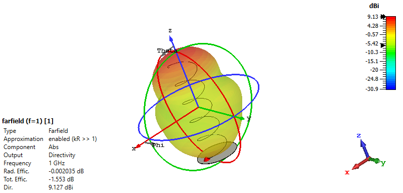
Figure 2.1 - 3D radiation diagram. Pattern visualization at 1 GHz. The pronounced and directional main lobe along the helix axis (+Z) is the unequivocal signature of operation in the desired axial mode.
2.3 Beam Quality and Circular Polarization
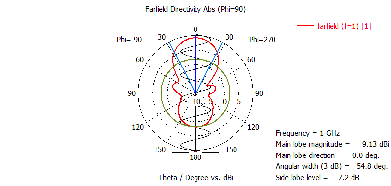
Figure 2.2 - Pattern cut (Axial plane) |
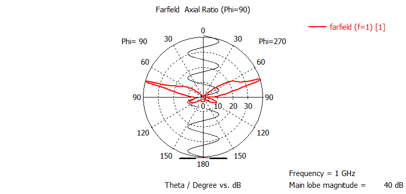
Figure 2.3 - Axial Ratio (AR) in the axial plane |
Figure 2.2 & 2.3 - Combined analysis. The pattern cut (Figure 2.2) quantifies directivity (9.13 dBi) and beamwidth (54.8°). The Axial Ratio plot (Figure 2.3) validates circular polarization quality: an AR value close to 0 dB in the axial direction (θ = 0°) confirms nearly perfect right-hand circular polarization (RHCP) at the heart of the main lobe, meeting the most demanding design objective of this antenna.
2.4 Pattern in the Transverse Plane
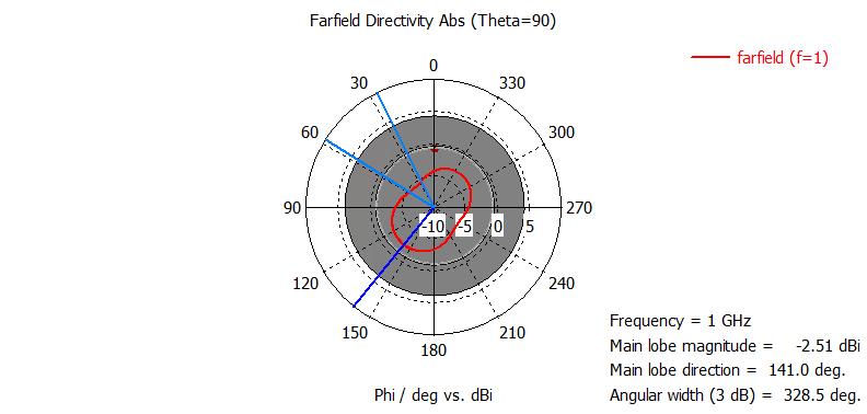
Figure 2.4 - Pattern in transverse plane. Cut in the XY plane (θ = 90°), perpendicular to the antenna axis. Shows low directivity (-2.51 dBi) and an almost omnidirectional pattern, confirming that radiation is effectively concentrated in front of the helix and does not scatter to the sides.
2.5 Design Conclusion
The design successfully achieves a helical antenna operating in axial mode, combining appreciable directivity with high-quality circular polarization. The axial ratio close to 0 dB on the beam axis is a particularly notable result, validating the precision of geometric dimensioning and correct mode excitation. This set of characteristics makes it an effective model for applications requiring circular polarization and directional radiation, such as in satellite links or telemetry.
3. Yagi-Uda Antenna for UHF (6 elements)
Design objective: Directional antenna for 550 MHz with directivity >10 dBi.
3.1 Design Parameters and Results
| Parameter | Value | Parameter | Value |
|---|---|---|---|
| Center frequency (f₀) | 550 MHz | Wavelength (λ) | 0.545 m |
| Achieved directivity (D₀) | 10.87 dBi | Return loss | 20.0 dB |
| Beamwidth (-3 dB) (E-plane) | 43.1° | Side lobe level (E-plane) | -10.5 dB |
| Total efficiency | -0.082 dB (∼98%) | Front-to-back ratio (approx.) | 10.9 dB |
3.2 Key Dimensions
Key dimensions (based on NBS Tech. Note 688):
| Element | Dimension |
|---|---|
| Reflector (L1) | 48.2 cm |
| Folded dipole (L2) | 24.8 cm |
| Directors (L3-L6) | 42.8 cm - 42.0 cm |
| Spacing between directors | 25.0 cm |
| Element radius (Al) | 2.32 mm (0.232 cm) |
3.3 Model and Antenna Response
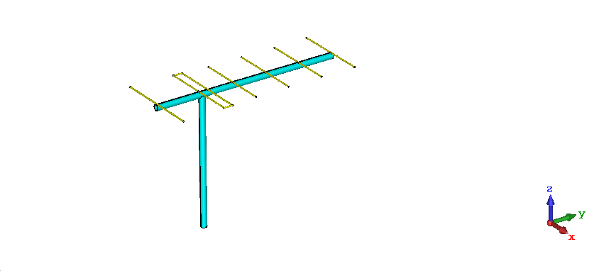
Figure 3.1 - Physical Model. Simulated structure with 6 elements: one reflector, one active folded dipole, and 4 directors. The conductive elements are hollow aluminum, mounted on a PVC support rod. The folded dipole, tuned for an impedance close to 200 Ω, is matched to 50 Ω using a 4:1 balun made with 50Ω coaxial cable, facilitating direct connection.
3.4 Radiation Characteristics
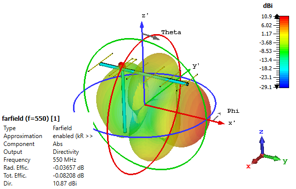
Figure 3.2 - 3D Radiation Pattern. Directivity diagram in logarithmic scale. Confirms directivity of 10.87 dBi and high radiation efficiency (-0.037 dB).
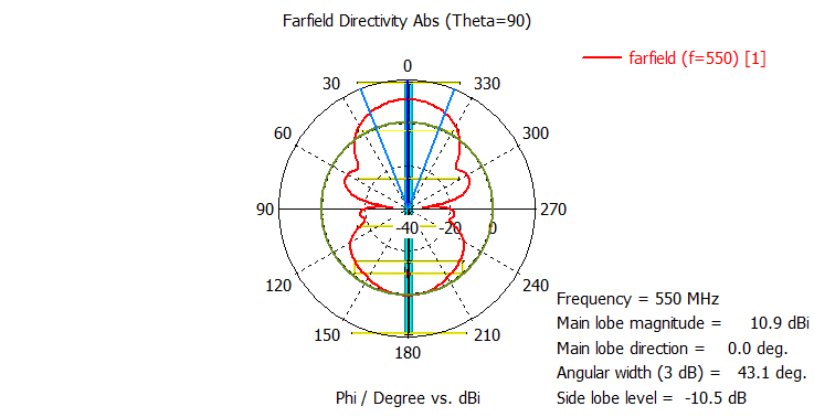
Figure 3.3 - E-plane Cut (top view, θ = 90°) |
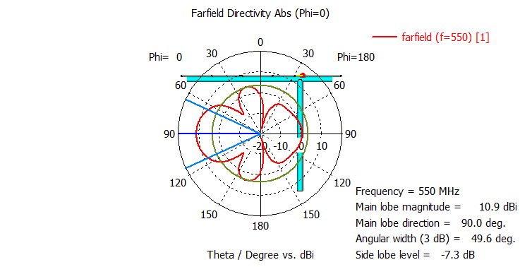
Figure 3.4 - H-plane Cut (side view, φ = 0°) |
Figure 3.3 & 3.4 - Principal Plane Cuts. The E-plane (containing the elements) shows the narrower main lobe (43.1°) and better side lobe suppression. The H-plane presents a slightly wider beam (49.6°).
3.5 Electrical Response and Matching
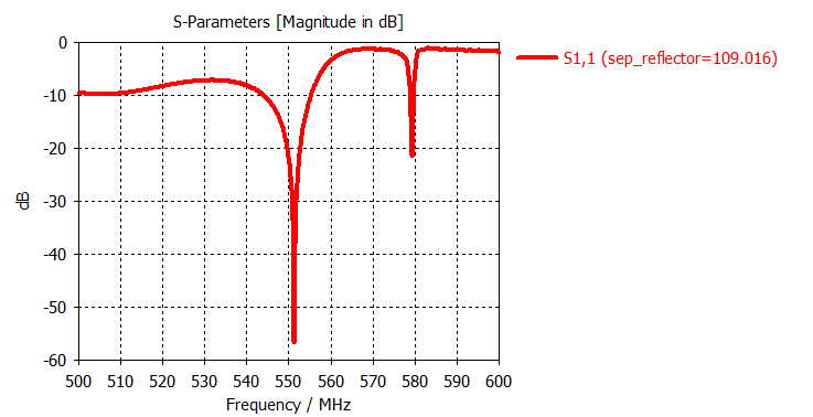
Figure 3.5 - Reflection Parameter (S₁₁). The curve shows a minimum of -20.0 dB at the center frequency of 550 MHz, exceeding the return loss requirement > 15 dB.
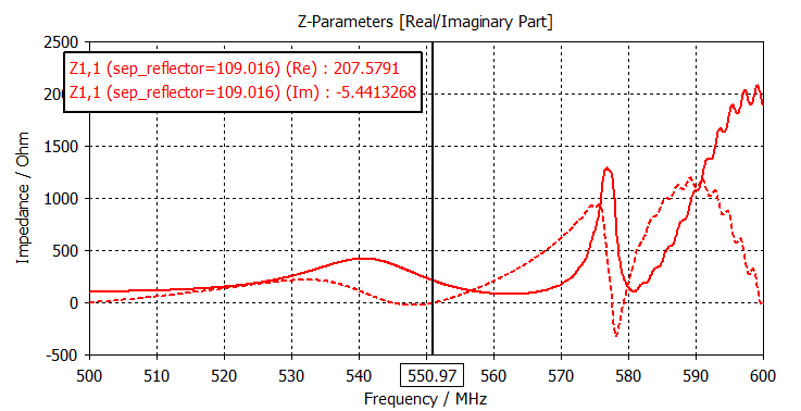
Figure 3.6 - Input Impedance (Zin). At 550 MHz, the impedance is Zin = 207.6 - j5.44 Ω. The real component close to 200 Ω is perfect for the 4:1 balun, and the small reactance (-j5.44 Ω) is negligible.
3.6 Design Conclusion
The design resulted in a practical, high-performance Yagi-Uda antenna for UHF, comfortably exceeding initial specifications. The choice of a folded dipole as the radiating element greatly simplifies matching: its natural impedance of ∼200 Ω perfectly matches a 4:1 balun constructible with a simple coaxial section, eliminating the need for printed circuits or discrete components.
4. Loop Antenna with 1.3 λ Perimeter
Objective: Analysis of a circular loop antenna with perimeter C = 1.3λ operating at 1 GHz, to study its characteristics in non-magnetic dipole mode due to its large electrical size.
4.1 Design Parameters and Results at f₀
| Parameter | Value |
|---|---|
| Operating frequency (f₀) | 1 GHz |
| Circumference perimeter (C) | 1.3λ |
| Conductor radius (Cu) | 4 mm |
| Maximum directivity | 4.38 dBi |
| Radiation efficiency | -0.0024 dB (∼99.9%) |
| Total efficiency | -4.86 dB (∼32%) |
4.2 Radiation Mode Characterization
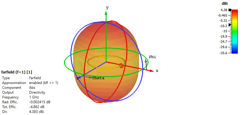
Figure 4.1 - Complex 3D pattern. For a 1.3λ loop, the diagram is no longer the simple toroid of a magnetic dipole. A multilobed structure is observed, indicative of non-uniform current distribution along the conductor, characteristic of electrically large loops.
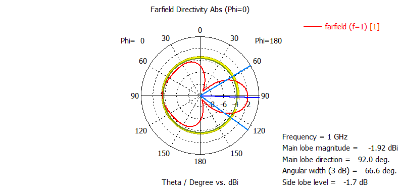
Figure 4.2 - E-plane Cut (φ = 0°) |
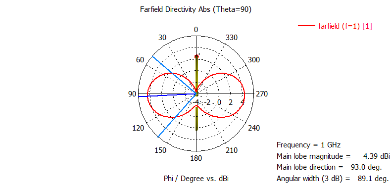
Figure 4.3 - H-plane Cut (θ = 90°) |
Figure 4.2 & 4.3 - E and H-plane patterns. Both cuts show pronounced secondary lobes and nulls, confirming that the antenna no longer operates in magnetic dipole mode. The measured directivity (4.38 dBi) is higher than that of a small loop.
4.3 Impedance Analysis and Frequency Response
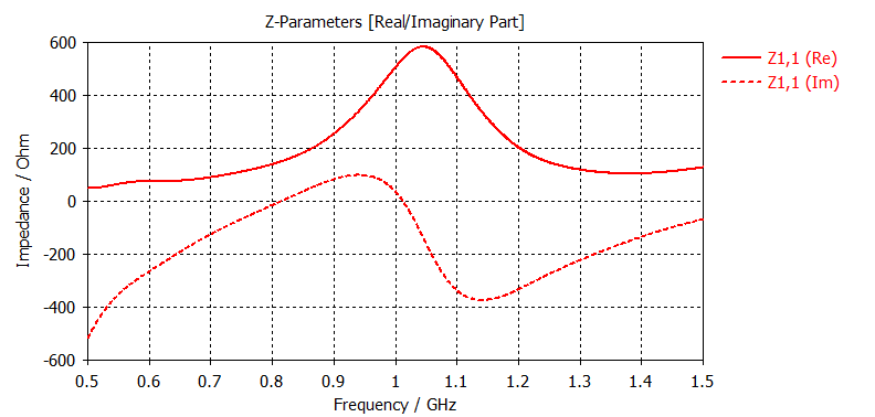
Figure 4.4 - Input impedance vs. Frequency. The plot shows the evolution of Z parameters in a sweep from 0.5 to 1.5 GHz. At the design frequency (1 GHz), the impedance is Zin ≈ 500 + j30 Ω.
The high radiation resistance (∼500 Ω) is a direct result of the loop's large electrical size (1.3λ), which moves it away from the low-impedance behavior of a magnetic dipole. This extreme mismatch with the port reference impedance (50 Ω) is the main cause of the low total efficiency (-4.86 dB), as it causes high power reflection despite the structure's excellent intrinsic radiation efficiency.
4.4 Analysis Conclusion
The simulation of the 1.3λ loop confirmed the distinctive properties of a large electrical size antenna: a complex, multilobed radiation pattern and high radiation resistance (∼500 Ω). The combination of excellent radiation efficiency with low total efficiency highlights the need for an impedance matching system in this type of design.