Key Specifications
| Parameter | Value |
|---|---|
| Center frequency | 1 GHz |
| Substrate | Rogers RT/duroid 5880LZ |
| Dielectric constant (εr) | 2.00 ± 0.04 |
| Dielectric thickness | 1.27 mm (0.05 inch) |
| Copper thickness | 35 μm |
| Line impedance (Z0) | 50 Ω |
| Arm impedance (Z) | √2·Z0 ≈ 70.7 Ω |
| Isolation resistor | 90 Ω (ideal 100 Ω) |
| Fabrication technology | CNC milling (Wegstr) |
| Measurement instrument | VNA Rohde & Schwarz ZNC3-2Port |
Design and Simulation
The design began with a schematic in Keysight ADS where λ/4 transformers and the isolation resistor were modeled. A balanced design was chosen (P2 = P3 = P1/2), meaning both outputs should show 3 dB attenuation relative to the input.
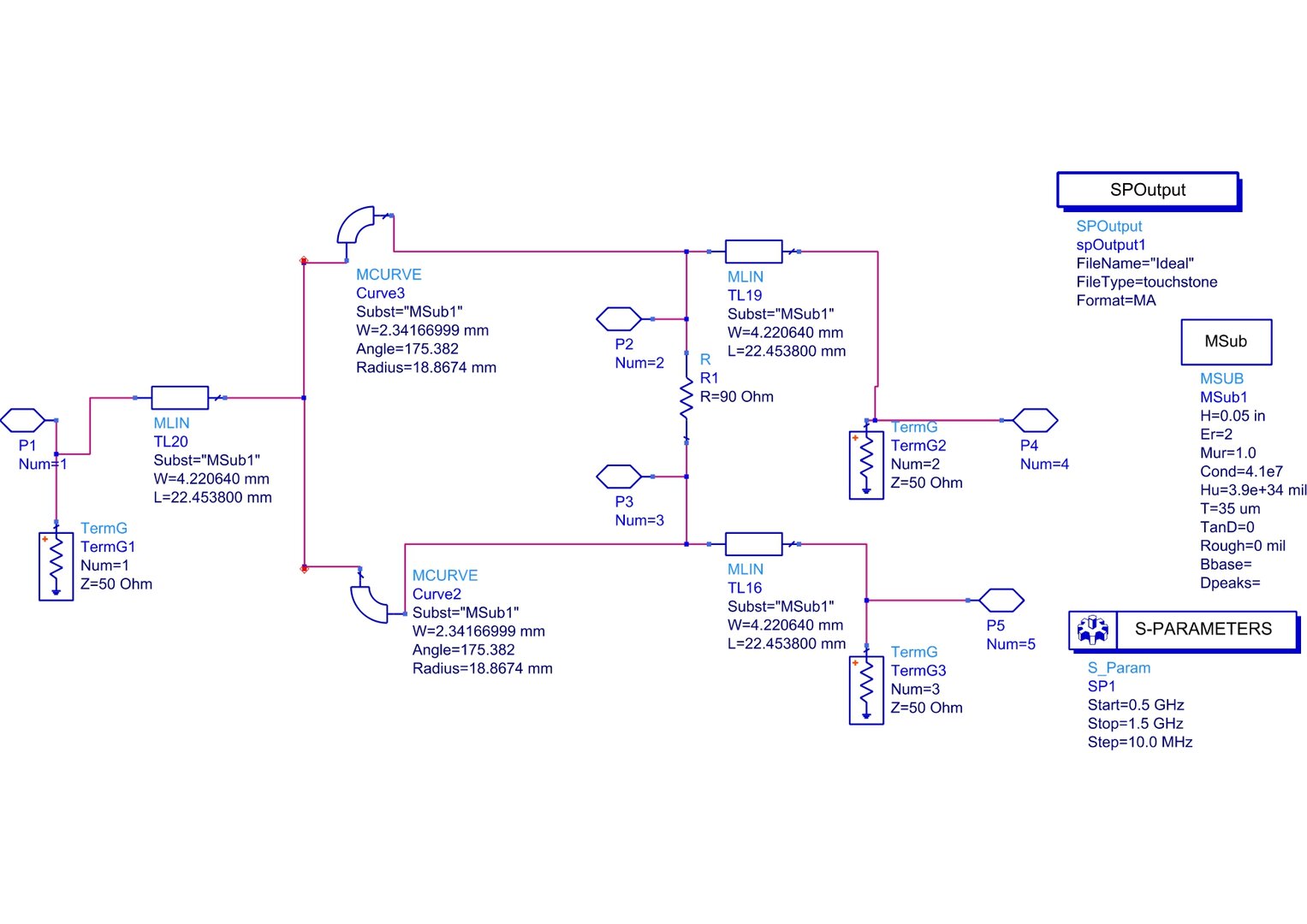
ADS schematic of Wilkinson divider.
Electromagnetic simulation showed near-ideal behavior in the frequency band of interest, although a slight frequency shift was observed attributed to differences between theoretical and actual substrate properties.
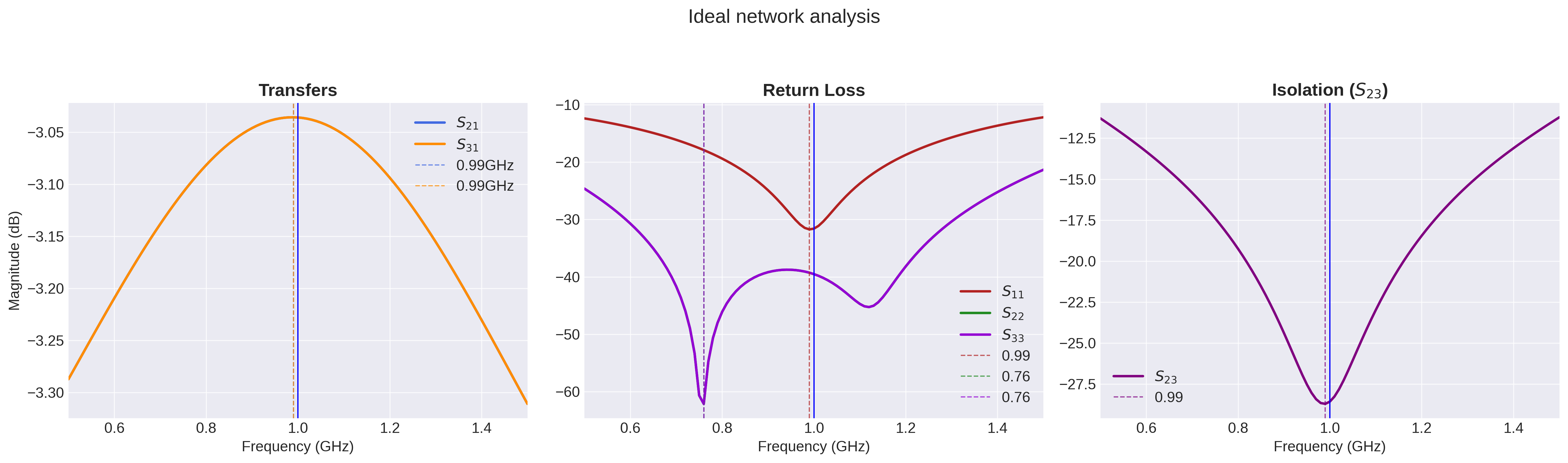
S-parameters of ideal network.
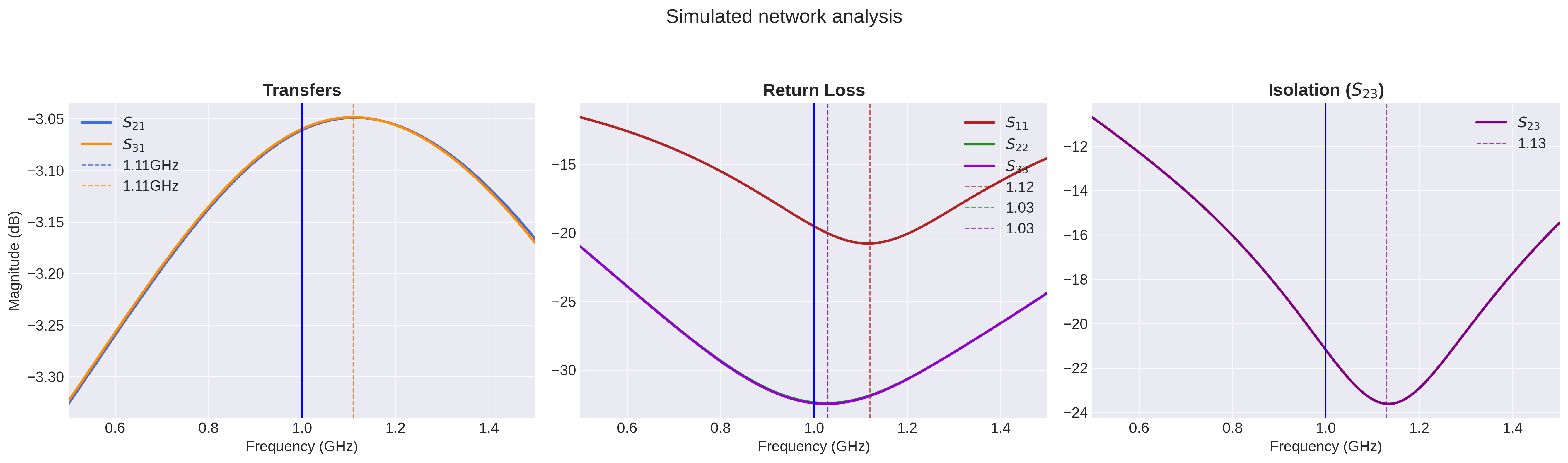
S-parameters of EM simulation.
CNC Router Fabrication
For the physical layout, straight sections were replaced with calculated radius arcs, which allowed maximizing isolation between traces and eliminating sharp angles that degrade RF performance.
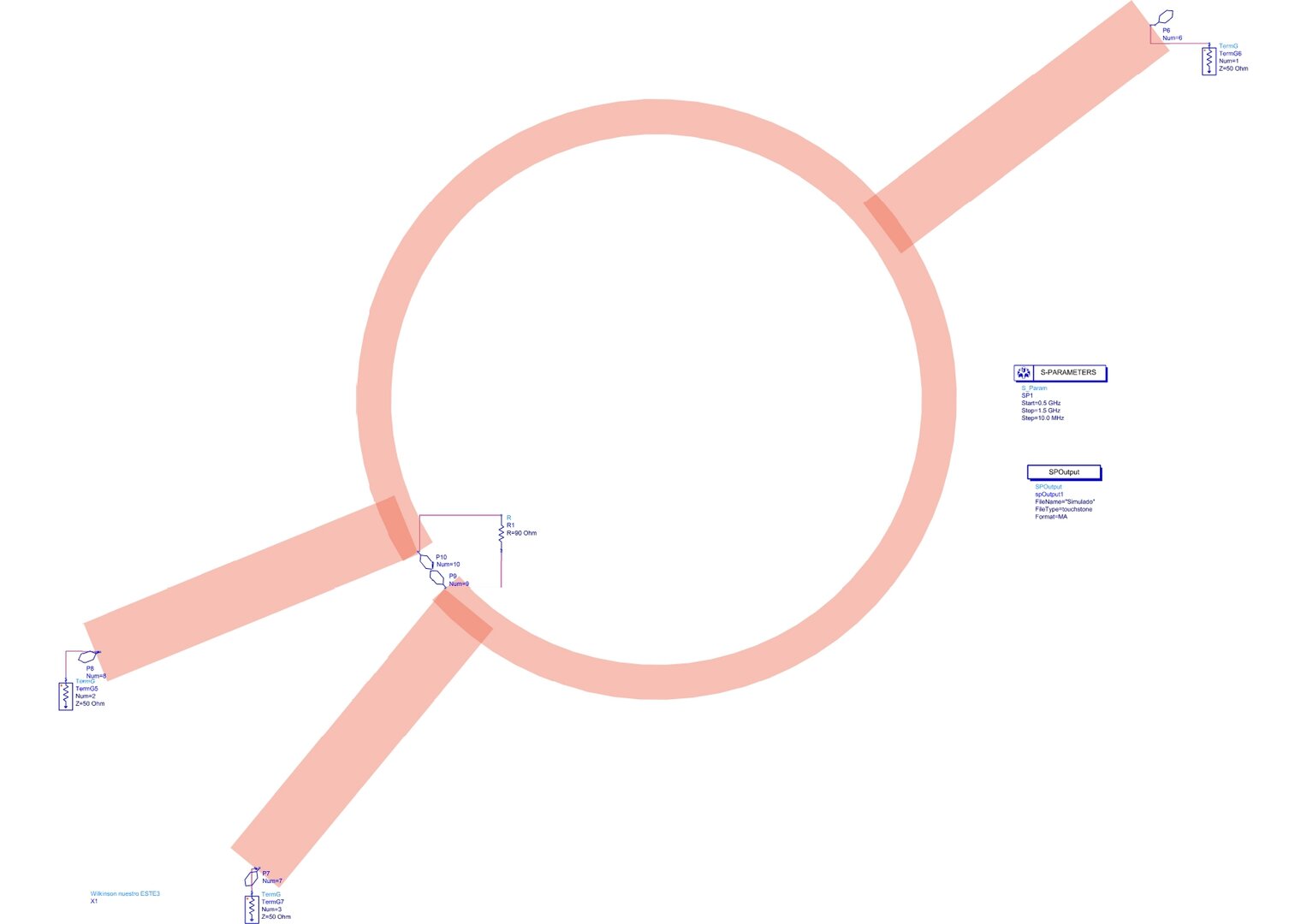
Electromagnetic simulation of the prototype.
Gerber files generated from the layout were sent to a Wegstr CNC mill with 0.02 mm repeatability. To reduce drill bit wear, a copper "fill" was manually added around the traces, maintaining approximately two trace widths separation between traces and ground.
The milling process was clean and precise, resulting in well-defined traces and sharp edges. SMA connectors were subsequently soldered to each port, and solder points were added to connect top and bottom ground planes, avoiding parasitic coupling.
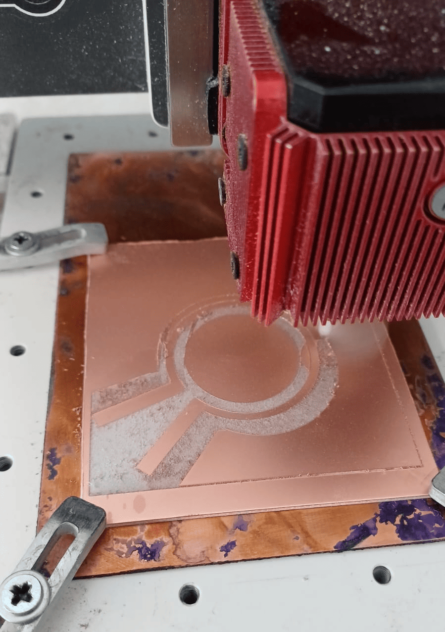
CNC router milling Rogers board.
Finished Prototype
The final device is compact, robust, and ready for measurement. SMA connectors allow direct connection to the VNA using calibration cables.
The 90 Ω resistor (visible in the center) was obtained by placing two 180 Ω SMD resistors in parallel, being the closest combination to the ideal value of 100 Ω available in the laboratory. Soldering these miniature components by hand was challenging, but they worked very satisfactorily. Special care was also taken when soldering the SMA connectors to avoid shorting the ground. Nevertheless, measured isolation exceeded -20 dB at the center frequency.
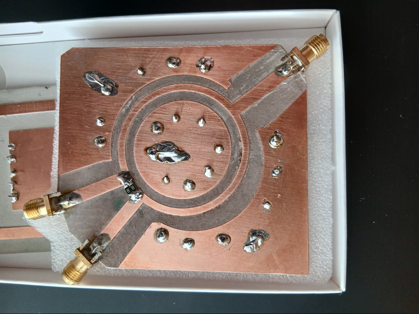
Finished Wilkinson divider with soldered SMA connectors.
Results and Validation
Measurements were performed with a Rohde & Schwarz ZNC3 vector network analyzer. The obtained S-parameters confirmed expected behavior:
- S21 and S31: ≈ -3 dB at 1 GHz → balanced division.
- S11: better than -20 dB → excellent input port matching.
- S23: better than -20 dB → high isolation between outputs.
Some ripple was observed in the frequency response, but additional tests ruled out the divider as the cause; rather, it was attributed to imperfections in measurement system cables and connectors.

Measurements of the finished device on VNA.

Gerber file view (decorative).
Detailed Analysis with Python
For deeper data processing, a Jupyter Notebook was developed with scikit-rf and matplotlib that allows:
- Loading S-parameter files (.s2p) from both simulation and VNA.
- Graphically comparing ideal, simulated, and measured responses.
- Applying corrections (such as cable de-embedding) and evaluating their effect.
The analysis is shown below. It can also be viewed here: Analisis.ipynb
Conclusion
The fabricated Wilkinson divider demonstrates professional-level RF implementation, meeting all critical specifications at the target frequency of 1 GHz. The project validates a comprehensive workflow combining high-level tools (ADS for EM simulation, Rohde & Schwarz VNA for characterization) with specialized materials (Rogers 5880LZ substrate) and precise fabrication techniques (CNC milling).
Notable achievements:
- Balanced division (-3 dB) with isolation >20 dB.
- Excellent matching at all ports (S11 < -20 dB).
- Clean and repeatable fabrication via CNC.
- Validated workflow: ADS → Gerber → CNC → VNA → Python.
Learning:
The discrepancy between simulated and measured frequency highlights the importance of using actual substrate properties from the initial design stage. For future iterations, iterative EM optimization would allow correcting this shift and further refining bandwidth.
Complete repository: https://github.com/SimonAulet/portfolio/blob/main/Wilkinson_power_divider/Analisis.ipynb
Tools: Keysight ADS, Wegstr CNC, Rohde & Schwarz ZNC3, Python (scikit-rf, matplotlib).